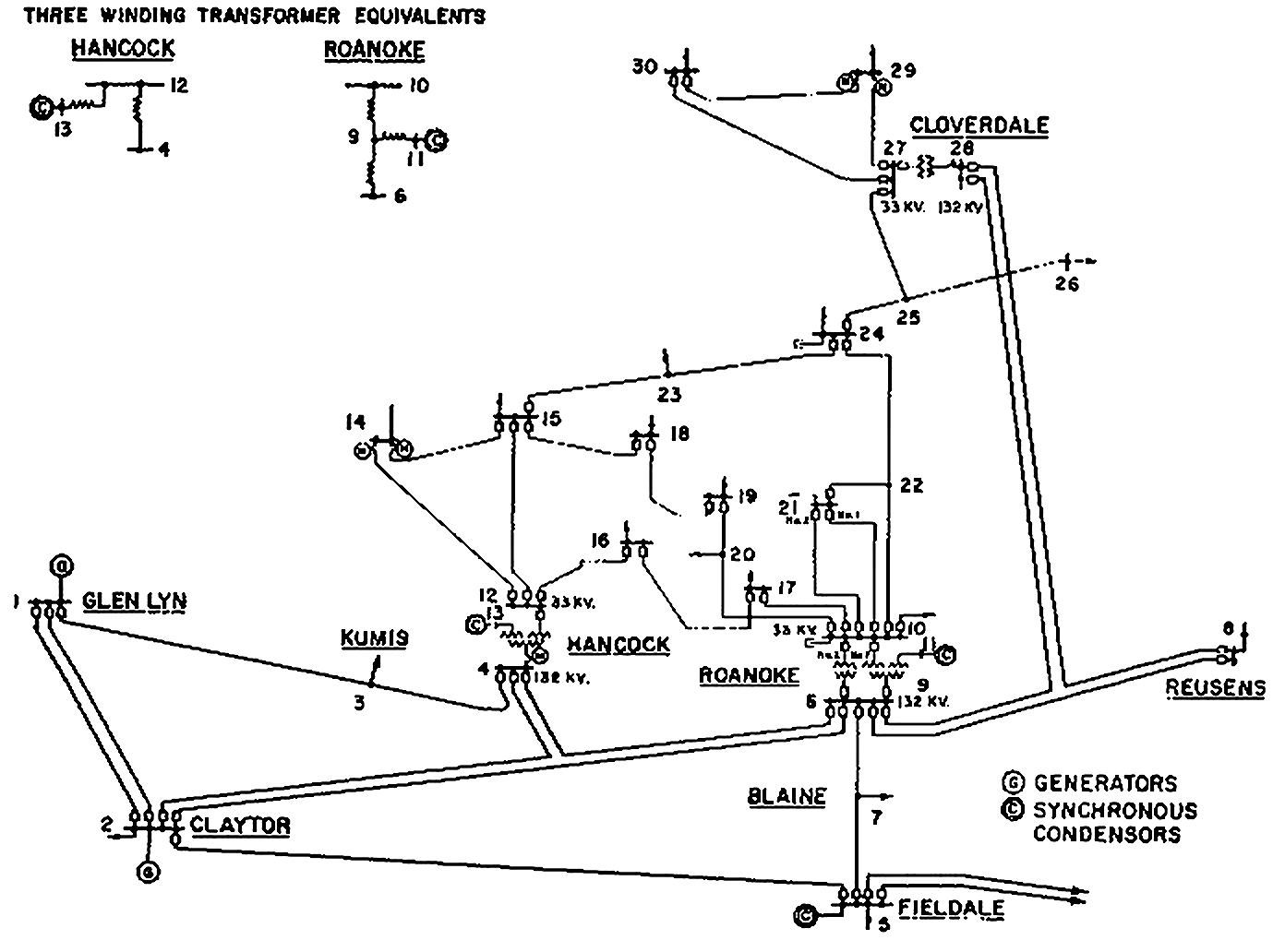
The standard IEEE 30 bus system consists of 30 buses 6 generators 24 loads and 4 trans- formers. Application of Parallel and Distributed Processing Mohammad Shahidehpour Yaoyu Wang Copyright 0 2003 John Wiley t Sons Inc.
The standard IEEE 30 bus system consists of 30 buses 6 generators 24 loads and 4 trans- formers.
Ieee 30 bus system. The IEEE 30-bus test case represents a simple approximation of the American Electric Power system as it was in December 1961 1. The equivalent system has 15 buses 2 generators and 3 synchronous condensers. The 11 kV and 10 kV base voltages are guesses and may not reflect the actual data.
The IEEE 30-bus test case represents a simple approximation of the American Electric Power system as it was in December 1961 1. The equivalent system has 15 buses 2 generators and 3 synchronous condensers. The 11 kV and 10 kV base voltages are guesses and may not reflect the actual data.
The IEEE 30 Bus Test Case represents a portion of the American Electric Power System in the Midwestern US as of December 1961. A hardcopy data was provided by Iraj Dabbagchi of AEP and entered in IEEE Common Data Format by Rich Christie at the University of Washington in August 1993. This test case consists of 15 buses 2.
This appendix presents IEEE-30 bus system data. This appendix presents IEEE-30 bus system data. In this paper we have used an IEEE- 30 bus as a test system and modeled it using PSAT software.
First we find the critical bus having a low voltage profile and then by trial and error method we searched for more efficient FACTS device at the appropriate location for maximum voltage enhancement of that critical bus. DATA FOR IEEE-30 BUS TEST SYSTEM The IEEE - 30 bus test system is shown in figure A1. The system data is taken from references 3.
The generator cost and emission coefficients load shunt capacitor data and bansmission lines re provided in the Tabla A1 A2 A3 and k4 respectively. The cost coefficients of IEEE-30 bus system are slightly modified to incorporate non-. IEEE 30 bus system.
In this bus system provided data form generation bus shunt capacitor transmission line load on bus. But MATLAB Simulink model calculated data for series admittance conductance and susceptance value of inductor and capacitor. 41 One line diagram of IEEE 30 bus system 41 Gauss- Seidel method In this method of solving for power system analysis the equation SVI is used where SPjQ and hence the equation becomes P jQ VI 1 P jQ VI 2 From the above equation we can deduce that the current I is given by.
30 Bus Power Flow Test Case The IEEE 30 Bus Test Case represents a portion of the American Electric Power System in the Midwestern US as of December 1961. The data was kindly provided by Iraj Dabbagchi of AEP and entered in IEEE Common Data Format by Rich Christie at the University of Washington in August 1993. Hi c14CASE14 Power flow data for IEEE 14 bus test case.
C30CASE_IEEE30 Power flow data for IEEE 30 bus test case. Case57CASE57 Power flow data for IEEE 57 bus. The program was run on an IEEE 30bus - system test network and the results were compared and validated for both the methods.
Both the Newton-Raphson method and the fast decoupled load flow method gave similar results. However the fast decoupled method converged faster than the NewtonRaphson method. The bus voltage magnitudes angles of each bus -.
The cost coefficients of IEEE-30 bus system are slightly modified to incorporate nonsmooth fuel cost functions with ramp rate coefficients as given in Table A5. The data is on 100 MVA base. For all analysis on this system V imin Vimax imin and imax for bus i are considered to be 09 pu 11 pu -45 degree and 45 degree respectively.
Communication and Control in Electric Payer Systems. Application of Parallel and Distributed Processing Mohammad Shahidehpour Yaoyu Wang Copyright 0 2003 John Wiley t Sons Inc. 0-471-45325-0 Appendix C IEEE-30 Bus System Data Cl BUS LOAD AND INJECTION DATA OF THE IEEE 30-BUS SYSTEM.
The standard IEEE 30 bus system consists of 30 buses 6 generators 24 loads and 4 trans- formers. Generator 1 is nw ng Mod e. The IEEE 30 bus system consists of 6 generators buses 24 load buses and 41 transmission lines.
The real load of the system is 2834MW and reactive load is 1262MVAR. GitHub - adilkhan095IEEE-30-Bus-System. Designed an IEEE 30 Bus system using PowerWorld performing Power flow and fault analysis on the system.
Avr_IEEET1- IEEE type 1 excitation system DigSILENT simulation language for Avr_IEEET1- IEEE type 1 excitation system incupss 0 incvuel 0 incvoel 0 incusetp xaKau incusetp u incVbias xaKa-vuelvoel incxr u incxe uerrs incxf uerrs incxa xeKe1Se. Power flow data for IEEE 30-bus test case. This data was converted from IEEE Common Data Format ieee30cdftxt on 15-Oct-2014 by cdf2matp rev.
See end of file for warnings generated during conversion. Converted from IEEE CDF file from University of Washington power systems test case archive.
