Fabrication Steps Start with blank wafer Build inverter from the bottom up First step will be to form the n-well Cover wafer with protective layer of SiO2 oxide Remove layer where n-well should be built Implant or diffuse n dopants into exposed wafer Strip off SiO2 p. Process flow for Fabrication of MOSFETs.

Nmos fabrication process wafer electronics semiconductor.
Mosfet fabrication steps ppt. Fabrication Process Flow. Basic Steps Figure 22 Fabrication of MOSFETs MR. HIMANSHU DIWAKAR JETGI 12 13.
Basic Steps Figure 23. The result of a single lithographic patterning sequence on silicon dioxide without showing the intermediate steps. Compare the un patterned structure top and the patterned structure.
Aim of course not to teach fabrication simply an overview of basic steps circuit designers need to understand process other classes provide details Lush Quiñones Zubia Basic steps photolithography pattern setting implantation add dopants to silicon deposition add new layers metals oxides. N-MOS Fabrication Process Step - Metallization Fig. 17 The region of photoresist which is not exposed by UV light will become soft.
This unpolymerised photoresist and SiO2 below it. MOSFETs MOSFETs have characteristics similar to JFETs and additional characteristics that make then very useful There are 2 types of MOSFETs. Depletion mode MOSFET D-MOSFET Operates in Depletion mode the same way as a JFET when VGS 0 Operates in Enhancement mode like E-MOSFET when VGS 0 Enhancement Mode MOSFET E-MOSFET Operates only in Enhancement mode.
Pmos Fabrication Steps PowerPoint PPT Presentations. 2013 - Metal-Oxide-Semiconductor Field-Effect Transistor Digital Logic Technology CMOS Fabrication MOS Device Structure and Operation NMOS Circuits CMOS Circuits. Metal-Oxide-Semiconductor Field-Effect Transistor Digital Logic.
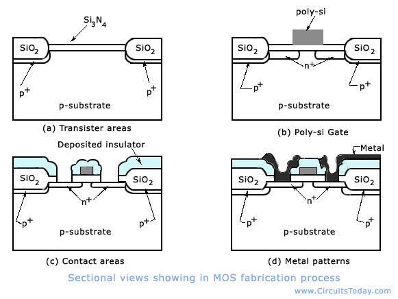
In this section we will examine the main processing steps involved in fabrication of an n-channel MOS transistor on a p-type silicon substrate. The first step of the process is the oxidation of the silicon substrate Fig 1244a. IC FABRICATION PROCESS PREPARED BY.
This occurs in a series of wafer processing steps collectively referred to as BEOL WAFER TEST DEVICE TEST DIE PREPARATION PACKAGING HAZARDOUS MATERIALS Poisonous elemental dopants - arsenic antimony and phosphorus poisonous compounds - arsine phosphine and silane Highly reactive liquids. An n or p substrate with lightly doped - epitaxial or epi layer - to protect latch up B. Grow high-purity silicon layers of controlled thickness b.
With accurately determined dopant concentrations c. Electrical properties are determined by the dopant and its concentration in Si. Fabrication Steps Start with blank wafer Build inverter from the bottom up First step will be to form the n-well Cover wafer with protective layer of SiO2 oxide Remove layer where n-well should be built Implant or diffuse n dopants into exposed wafer Strip off SiO2 p.
For less power dissipation requirement CMOS technology is used for implementing transistors. If we require a faster circuit then transistors are implemented over IC using BJTFabrication of CMOS transistors as ICs can be done in three different methods. The N-well P-well technology where n-type diffusion is done over a p-type substrate or p-type diffusion is done over.
In early 1960s the semiconductor manufacturing process was initiated from Texas and in 1963 CMOS or complementary metal oxide semiconductor was patented by Frank Wanlass. Integrated circuits are manufactured by utilizing the semiconductor device fabrication process. These ICs are major components of every electrical and electronic devices which we use in our daily life.
Fabrication Steps Start with blank wafer Build inverter from the bottom up First step will be to form the n-well Cover wafer with protective layer of SiO 2 oxide Remove layer where n-well should be built Implant or diffuse n dopants into exposed wafer Strip off SiO 2 p substrate. There are a huge number and assortment of fundamental fabrication steps utilized as a part of the generation of present-day MOS ICs. A similar procedure can be utilized for the planned of NMOS or PMOS or CMOS devicesThe most commonly used material could be either metal or poly-silicon.
Process flow for Fabrication of MOSFETs. INTRODUCTION TO VLSI TECHNOLOGY MOORES LAW AND ITS LIMITATIONS LIMITATIONS ON MOSFET TECHNOLOGY SHORT CHANNEL EFFECT IN MOSFET INTRODUCTION TO FINFET WHY WE NEED FINFET STRUCTURE OF FINFET FABRICATION PROCESS OF FINFET ADVANTAGES AND DISADVANTAGES OF FINFET. UNIT 1BASIC MOS TECHNOLOGY nMOS fabrication There are a large number and variety of basic fabrication steps used in the production of modern MOS ICs.
The same process can be used for the designed of NMOS or PMOS or CMOS devicesThe gate. Bicmos fabrication process steps pdf The basic patterning process used in all fabrication steps however is quiteCMOS fabrication sequence. Thin gate oxide is grown onDiffusion Ion implantation Deposition Fabrication steps p-Well process n.
Pmos fabrication process steps ppt Metaloxidesemiconductor MOS fabrication is the process used to. Cmos fabrication and its implications. Corporate institute of science technology bhopal.
Nmos fabrication steps youtube. Pmos fabrication vlsi youtube. Nmos fabrication process wafer electronics semiconductor.
Explain the p-well process for cmos fabrication.