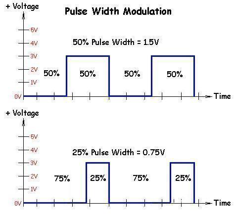
A modulation technique where the width of the pulses of the pulsed carrier wave is changed according to the modulating signal is known as Pulse Width Modulation PWM. Pulse Width Modulation or PWM is a common technique used to vary the width of the pulses in a pulse-train.

Case Aim Command Capstan Sharpshooter Raven Hawkeye and TeeJet DynaJet are Pulse-Width-Modulation PWM technologies where a pulsing solenoid controls flow rate through the nozzles.
What does a pulse width modulator do. The length of time that a pulse is in a given state highlow is the width of a pulse wave. The blue lines are PWM output from an MCU and the red line is the average voltage. In this case the pulse width and corresponding duty cycle change so that the average voltage looks more like an analog output that is not in a steady state such as shown in Figure 1.
Pulse Width Modulation PWM is a nifty current control technique that enables you to control the speed of motors heat output of heaters and much more in an energy-efficient and usually quieter manner. What Does A Pulse Width Modulator Do. A pulse width modulator regulates the amount of electrical current delivered to an HHO generator.
As a dry cell of an HHO generator produces HHO oxy-hydrogen gas the dry cell heats up. Pulse Width Modulation PWM Definition. A modulation technique where the width of the pulses of the pulsed carrier wave is changed according to the modulating signal is known as Pulse Width Modulation PWM.
It is also known as Pulse duration modulation PDM. Pulse width modulation turns a digital signal into an analog signal by changing the timing of how long it stays on and off. The term duty cycle is used to describe the percentage or ratio of how long it stays on compared to when it turns off.
One widely-used approach is pulse width modulation PWM that controls the power switch output power by varying its ON and OFF times. The ratio of ON time to the switching period time is the duty cycle. Pulse Width Modulation or PWM is a common technique used to vary the width of the pulses in a pulse-train.
PWM has many applications such as controlling servos and speed controllers limiting the effective power of motors and LEDs. Pulse Width Modulation PWM is a technique to generate low frequency output signals from high frequency pulses. Rapidly switching the output voltage of an inverter leg between the upper and lower DC rail voltages the low frequency output can be thought of.
Pulse Width Modulation PWM Tutorial 2 Comments At its core pulse width modulation PWM is just another modulation technique like AM or FM among others. Many electronics hobbyists who build robots and other moving things recognize the term as it pertains to controlling the speed of a motor. Pulse width modulation uses transistors which switch the DC voltage on and off in a defined sequence to produce the AC output voltage and frequency.
Im using an Arduino pulse-width modulation output to act as a throttle signal to a golf-cart motor controller. As I understand it the output looks like 500 Hertz and may cause an audible buzz in the motor operation. But I cant figure out what the 500 Hertz really means.
Does the Arduino go through the 256-bit cycle 500 times a second. How does a Pulse Width Modulation Charge Controller Work. The purpose of Charge Controller is to ensure efficient charging and discharging of system battery or a bank of batteries.
PWMs help to regulate the often inconsistent voltage put out by power sources for example solar panels in order to protect the system batteries from overcharging. Pulse Width Modulation or PWM is a digital technique to enable the proportional control of analog devices more efficiently. It generates variable-width pulses to represent the amplitude of an analog input signal.
The output switching transistor is on more of the time for a high-amplitude signal and off more of the time for a low-amplitude signal. Case Aim Command Capstan Sharpshooter Raven Hawkeye and TeeJet DynaJet are Pulse-Width-Modulation PWM technologies where a pulsing solenoid controls flow rate through the nozzles. The solenoid is installed in place of the diaphragm check valve and shuts off the nozzle flow for a split second exactly 10 times per second.
As its name suggests pulse width modulation speed control works by driving the motor with a series of ON-OFF pulses and varying the duty cycle the fraction of time that the output voltage is ON compared to when it is OFF of the pulses while keeping the frequency constant.