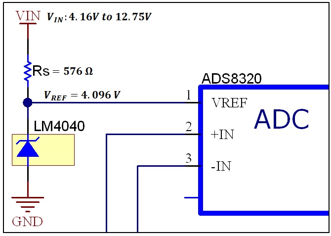
The voltage we like to measure must be lower than the voltage on the reference. ADCs convert analog inputs that can vary from zero volts on up to a maximum voltage level that is called the reference voltage.

The default analog reference of 5 volts on 5V Arduino boards or 33 volts on 33V Arduino boards INTERNAL.
What is reference voltage in adc. Analog-to-digital converters ADCs need a reference voltage V REF input in order to operate properly. ADCs convert analog inputs that can vary from zero volts on up to a maximum voltage level that is called the reference voltage. The reference voltage determines the ceiling of what the ADC can convert and is essentially the yardstick against which every proportion and result is.
The reference voltage generally known as Vref is usually the maximum voltage value that the DA converter can reach. This value depends on what is connected to the Vref pin. In your case what you mean as the reference voltage is the minimum step of your DAC and it corresponds to the number 000001.
What you mean as the reference voltage is the resolution of the converter. Analog-to-digital converters ADCs need a reference voltage V REF input in order to operate properly. ADCs convert analog inputs that can vary from zero volts on up to a maximum voltage level that is called the reference voltage.
The reference voltage determines the ceiling of what the ADC can convert and is essentially the yardstick against which every proportion and result is. ADCs convert analog inputs that can vary from zero volts on up to a maximum voltage level that is called the reference voltage. The reference voltage determines the ceiling of what the ADC can convert and is essentially the yardstick against which every proportion and result is measured.
Therefore in choosing a reference voltage VREF the voltage output. How the voltage reference affects ADC performance Part 2 Introduction This article is Part 2 of a three-part series that investigates the design and performance of a voltage-reference system for a successive-approximation register SAR analog-to-digital converter ADC. A simplified version of this system is shown in Figure 1.
When a design uses an ADC in this. That is the ADC Reference voltage. By default the power supply voltage is used so if you run your Arduino on 5 V then 1023 5 V.
But if you run your Arduino on 33 V then 1023 33 V. There is also in internal reference of 256 V or 11 V depending on your Arduino if you use that then you guessed it 1023 256 V or 11V. The fundamentals of ADCs Figure 1 shows the voltage-reference system for the successive-approximation-register SAR ADC that will be examined in this three-part series.
As the name suggests the ADC converts an analog voltage to a digital code. Hi to all how can i set reference voltage for ADC in psoc1. Here i want to set reference voltage 25v.
UNDERSTANDING AND MINIMISING ADC CONVERSION ERRORS VAREF is the reference voltage used by ADC for conversions. The details are mentioned in Section 25 After this comparison is done the next significant bit is set VAREF4 and a comparison is done again with the input voltage. The procedure is followed till all the bit positions are com-.
The actual generated reference voltage is 1024 V but with the help of programmable gain amplifiers it can be amplified by 1x 1024 V 2x 2048 V or 4x 4096 V to produce the three possible voltage levels. The FVRCON register shown below is used to. The Voltage Reference Vref component allows you to provide a stable precision reference voltage for the analog resources in your design.
Each component instance represents a physical analog reference source in the PSoC device. I had a few questions about the ADC in the MSP430G2231 Launchpad version. I know the reference voltage can be several different things 15v 25v some arbitrary voltage that I apply externally to a pin.
What are all the different choices for pre-set and non-preset reference voltages. What is the reference voltage selected for ADC polling example application adc_12b1msps_sar_polling in IMXRT1050 SDK. Contributor I Mark as New.
Subscribe to RSS Feed. Email to a Friend. Going through the application code for adc.
The voltage reference provides an accurate and stable point for the ADC and DAC for their conversions. A voltage reference can be picked with different levels of voltage accuracy and temperature stability. Your main power supply will fluctuate with different current draws and temperatures and can change based on current conditions.
Analog-to-digital converters ADC work very similar. They can take a voltage for example from one of the pins and calculate a difference to another reference. There is just one little difference here.
The voltage we like to measure must be lower than the voltage on the reference. A single external reference voltage applied to all reference inputs of the ADC array. Such a configuration lets you engineer an external reference voltage of arbitrary accuracy but incurs error due to small variations among the resistor ladders one ladder internal to each ADC.
Vref would provide maximum adc voltage that you can setIf you need more precision go with low Vref and a well dedicated hardware for glitch reduction. The default analog reference of 5 volts on 5V Arduino boards or 33 volts on 33V Arduino boards INTERNAL. A built-in reference equal to 11 volts on the ATmega168 or ATmega328P and 256 volts on the ATmega32U4 and ATmega8 not available on the Arduino Mega INTERNAL1V1.
A built-in 11V reference Arduino Mega only.